The electric fan conversion is complete!
Over the weekend I employed The Evil German Dude and the newly named Paparazzi Ford (Butch) to assist in the install of the electric fans. As this will be a somewhat lengthy post let me start by saying, thank you Frank. Without you this project would have been completed but would have been no where near as freaking awesome as it turned out.
Butch, thank you for taking WAY too many pictures photo-chronicalling this project. Butch said we should do some video blogging. I think he is on to something. He was none too happy about being relegated to the camera for this project but he cheerfully took pictures through out the 8 hour event.
If you don’t get together with your friends and do projects like this, I feel sorry for you. You are seriously missing out on some of the best stuff you can experience with friends. I’ve known and worked with these two guys since June of 2000 and their friendship is something I cherish deeply. We always have a really good time together. Man Bonding Time or as the Evil German Broad says, “babysitting Frank so I can watch football.” is some of the best stuff in the known universe.
I’d also like to thank the Evil German Broad for preparing us the delicious meals and reporting the scores in the Seahawks/Saints game for us. Mrs. Okierover was actually a little put off when she offered me breakfast that morning and I declined because as I said, “I get to eat breakfast at Bettina’s.”
 |
| Evil German Broad |
Not only are Garage Days at the Evil German Dude’s a culinary treat they are educational. EGD’s education in Germany and his experience in fabricating make projects like this an educational event. I don’t think there has been a Garage Day where I didn’t learn something from him.
This is a Huge Post
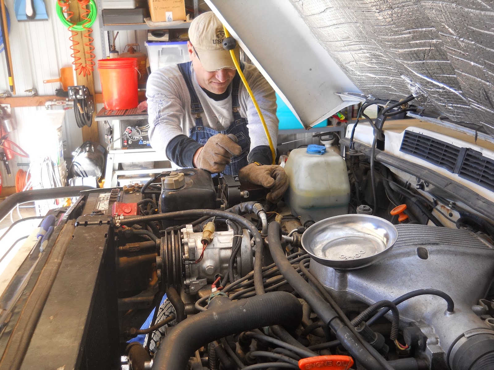
This project started at 0930 and didn’t get wrapped up until 1830. We took three breaks, one for breakfast, one for lunch, and one to weld up the exhaust leak. Butch and I mostly watched the whirlwind that is the Evil German Dude. It is his shop and only he knows where all the entrances to his secret earthquake generation lab tools are located. Overalls are not required but highly recommended. Two of the three of us (the smarter ones) were wearing them. So sit back and put on your reading glasses, you are going to need them for this one.
We gathered in the evil liar and had some fun. EGD had just shown us his new Harley Davidson money pit. We talked about all the silly accessories and how much they all cost. The last thing he showed us was the Official Harley Davidson® Motorcycle Tie-Down Straps™ in virgin black lamb’s wool.
 |
Virgin lamb’s wool Harley Davidson Tie Down Straps.
Sooooo soft. Sooooo expensive. |
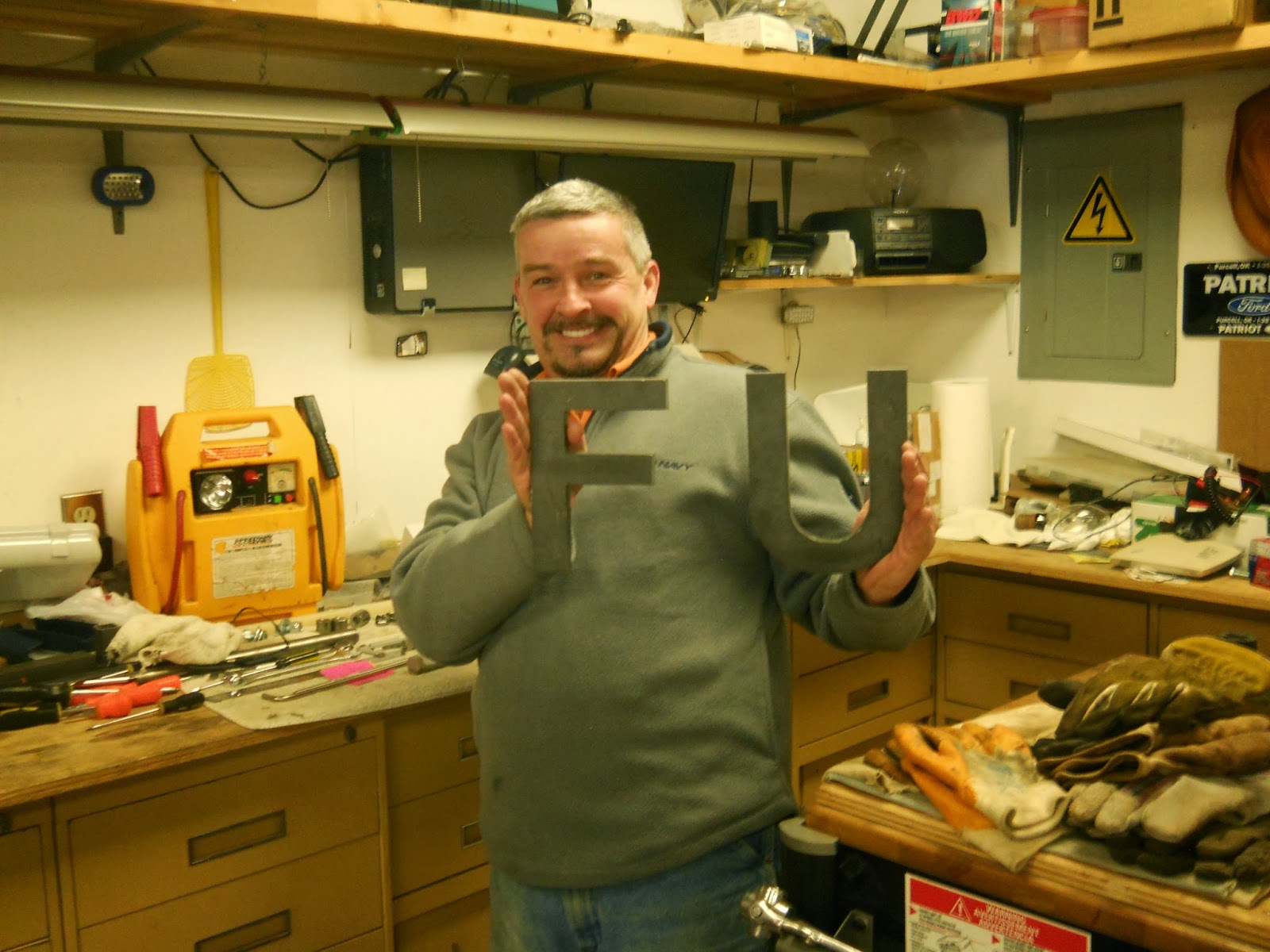
We taunted him quite excessively for thirty minutes and he then showed us some letters he found at a garage sale.
Breakfast and the non-electric-fan fun was over and it was time to get to work.
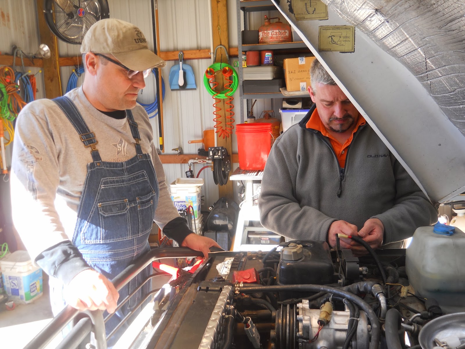
 |
| We were pretty sure who was in charge when we got started. |
I am going to list the things we did in the order, more or less, we did them.
This is custom fabrication so I feel like I should offer the following disclaimers:
- Not responsible for direct, indirect, incidental or consequential damages resulting from any defect, error or failure to perform.
- Your results may vary.
- All models are over 18 years of age.
- Discontinue use if rash develops.
- Not to be combined with other radioisotopes except under the advice of a physician.
- Void where prohibited except where not prohibited.
I think you get the idea. This install worked for my Range Rover. You will need to consider that your Range Rover may be slightly different than mine. Take your time and check your work as you go.
Plan
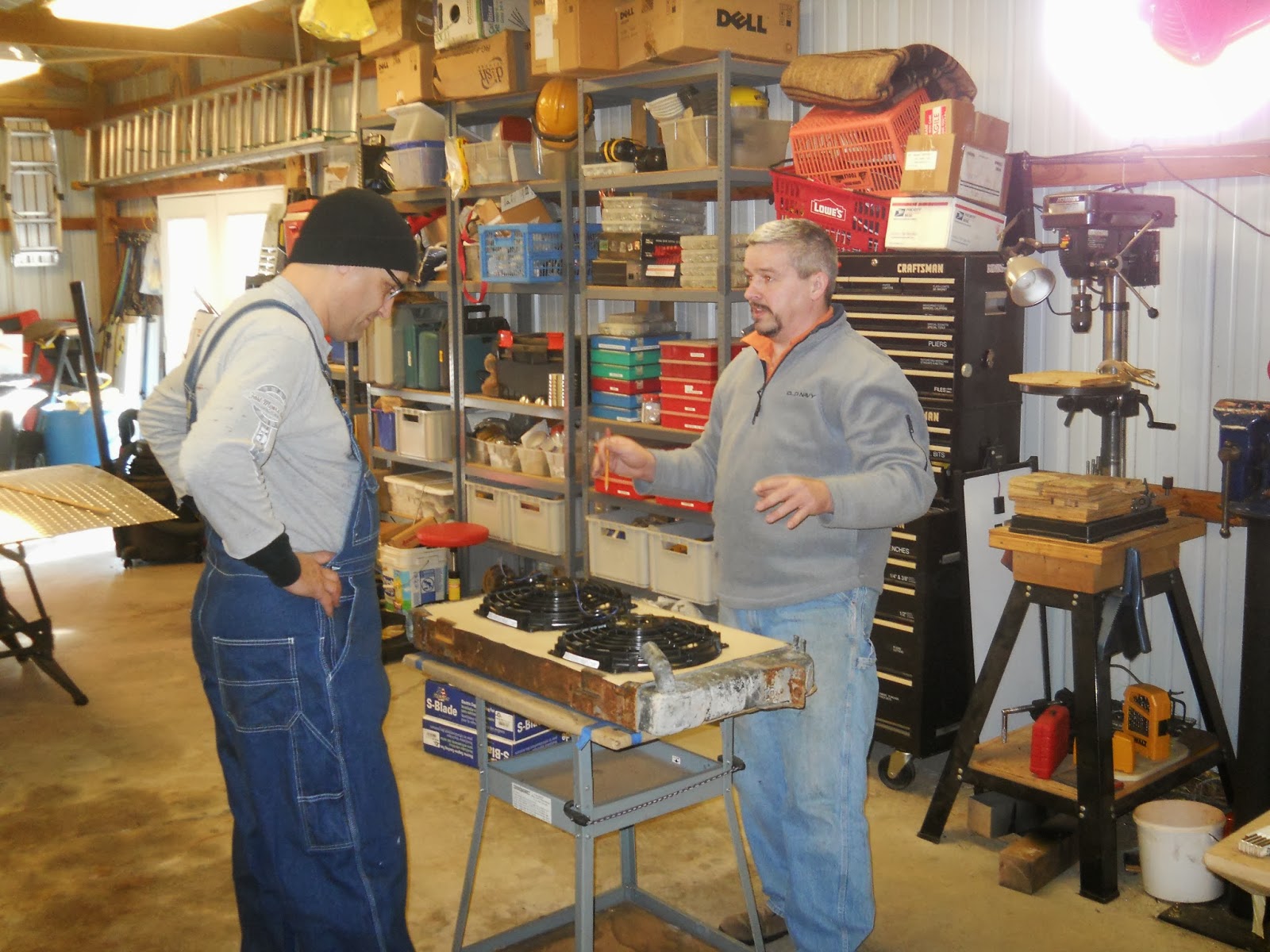
EGD and I had a planning meeting before we started. We looked at my extra radiator and took some measurements to determine fan size. We chose two 12 inch fans as we determined they would fit well on the radiator.
 |
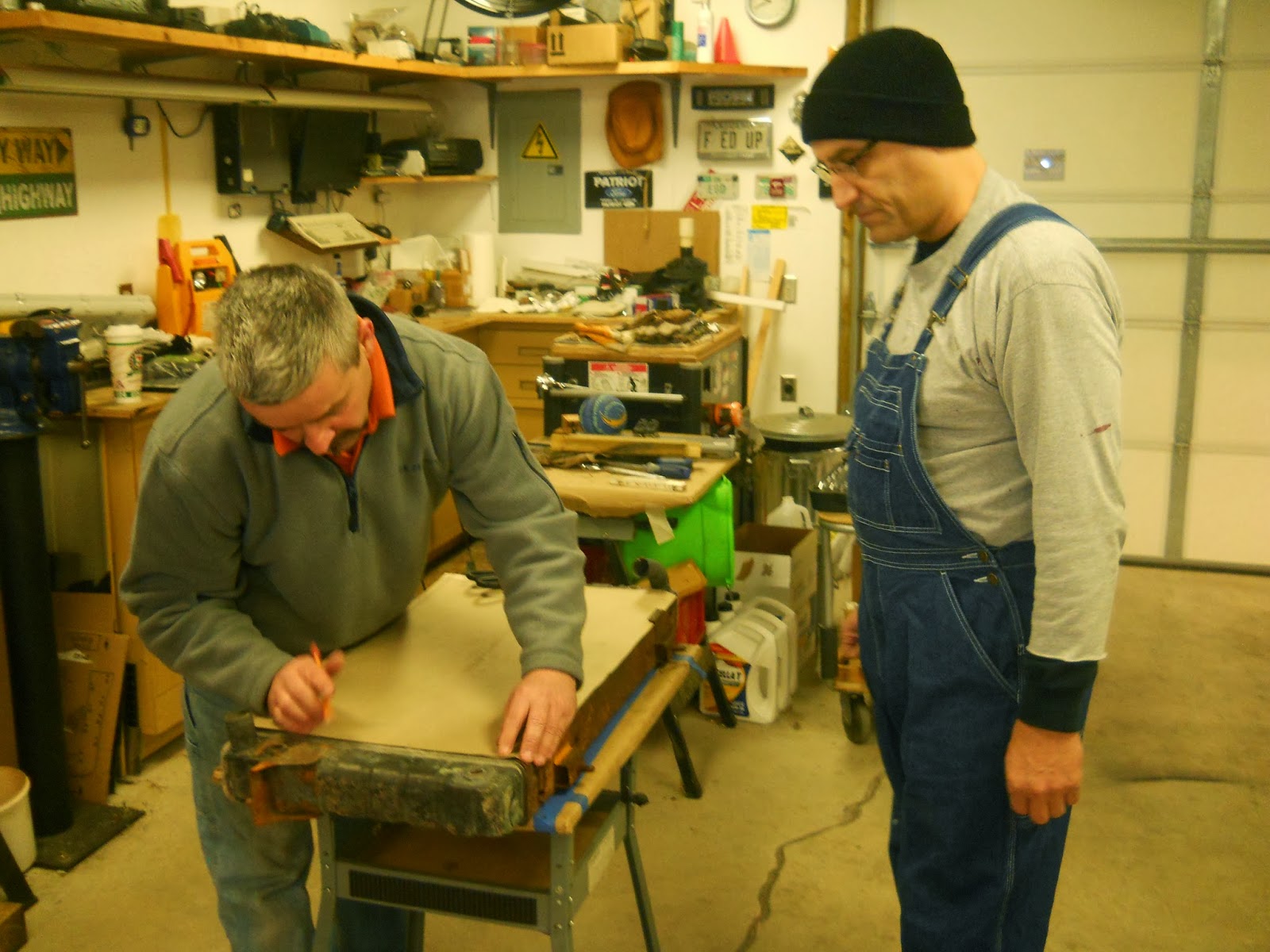
Lots of measurements were taken.
I was instructed to make a measured drawing and it was completely ignored. |
 |
| Staggered. One fan high on the left for the intake and one low for the exit. |
Gather Your Materials
Have everything ready and on-hand. Nothing makes a project drag on like having to stop and run to the auto parts store or the hardware store. I bought the fans and controller two weeks prior to install.
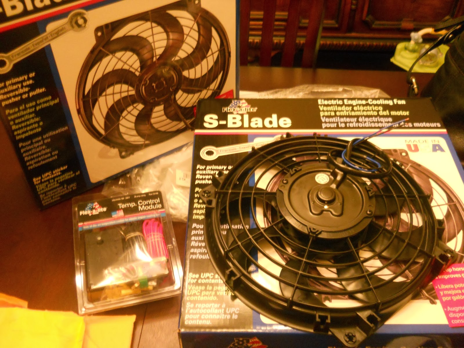
 |
Flex-a-lite twelve inch fans and controller from Summit Racing.
Around 280$(US). |
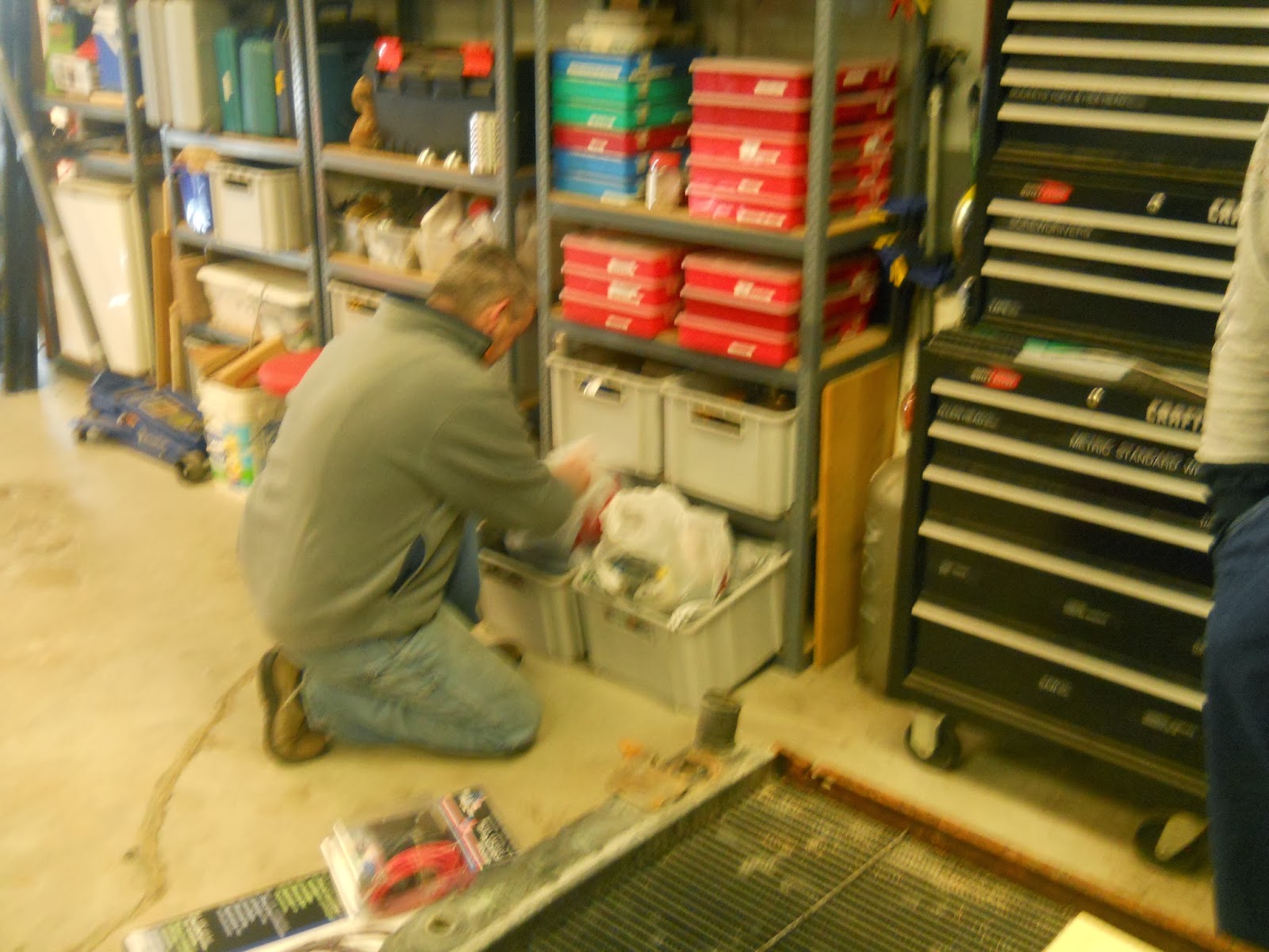
EGD has every fastener known to man in stainless steal, metric and standard, a “make NASA jealous” quantity of electrical connectors and wire, he had the aluminum diamond plate on hand (just to be safe it was a 4×6 foot sheet), zip ties (in several colors), heat shrink (multiple colors).
Think about how many bolts you’ll need. You can figure on needing a few dozen. But as I’ve always said you can never have enough fasteners. And for God’s sake use stainless steel fasteners. I swear if you use PLASTIC on a Land Rover it will rust. So do yourself a favor and minimize that as much as you can.
 |
NASA engineers wish they had the supplies EGD has on hand.
Butch was still training on the camera so we had some blurry pictures.
He didn’t start drinking beer until later. |
 |
| (Spock voice) “Impressive.” |
You’ll need to have the proper tools on hand as well. We used scissors, box knives, wrenches, sockets, drill press, tin snips, hammers (dead blow and metal working), jigsaw, gloves, metal shear, soldering gun, wire snips, electrical connector crimper, heat gun (for heat-shrink), a cable-fishing rod, hand drill, deburring bits, drill bits, air grinder, pop rivets, quick square, Sharpie® permanent markers, measuring tape, screw drivers, bolt cutters (we had to fix the battery cables), volt-ohm meter, bench vice, Sears Craftsman® work table (used to work on and to clamp for the 90 degree bend), air chisel, air compressor. That’s about it. You can substitute or improvise where necessary.
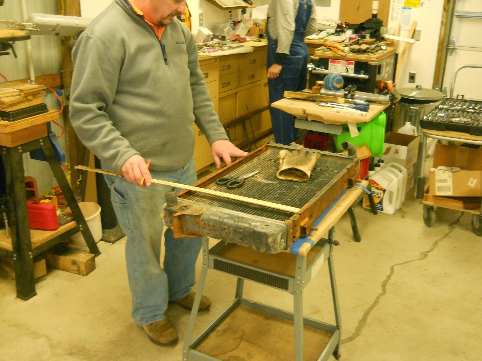
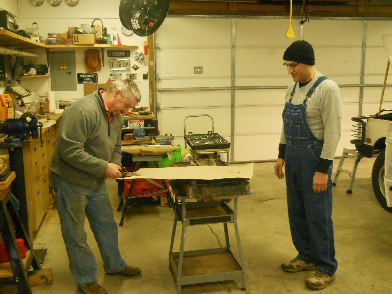
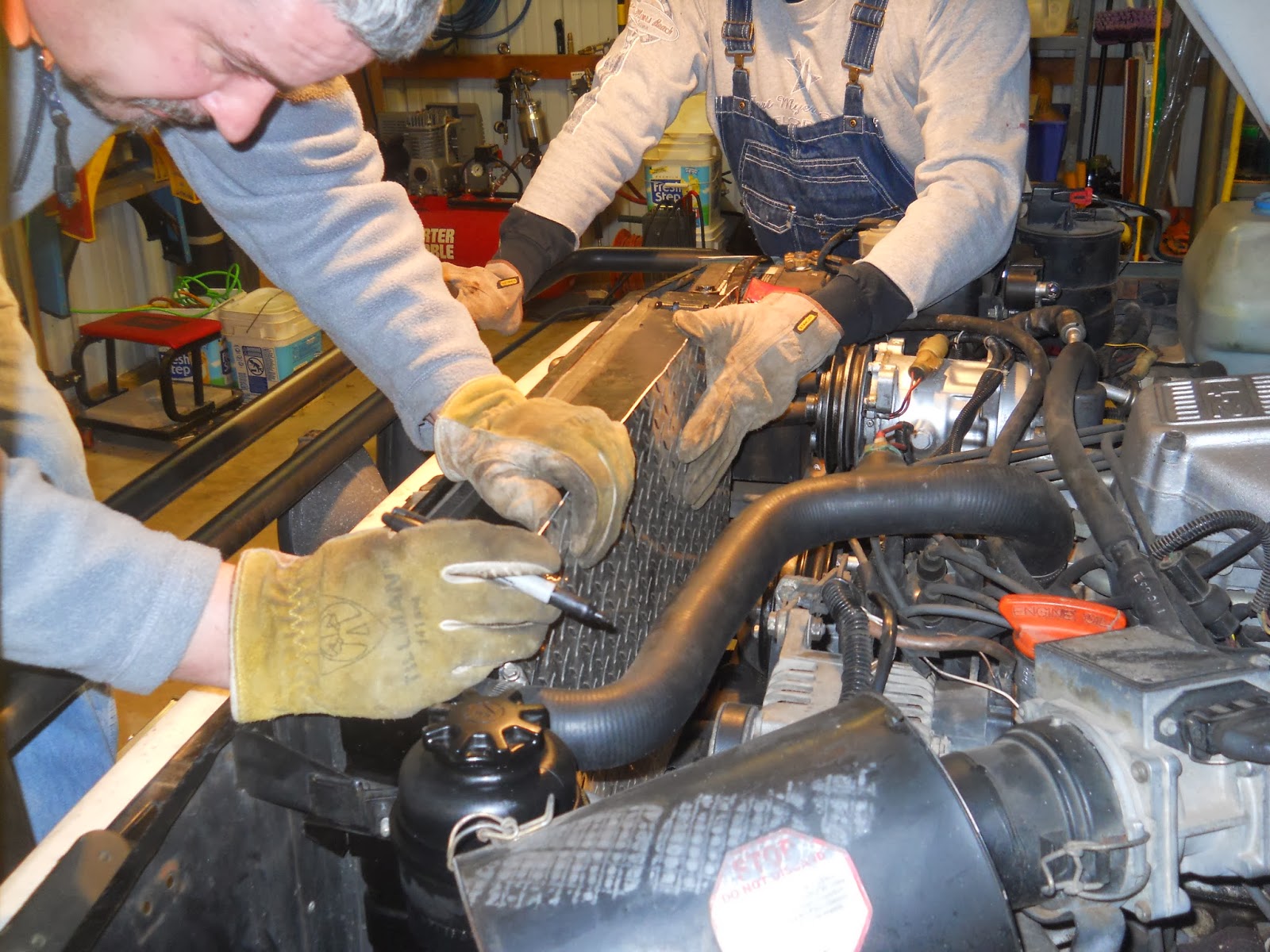
Measuring
Measure your radiator. Measure it again. Make a measured drawing. Examine how the existing shroud is installed. Remember to measure your engine bay clearances as well. We knew ahead of time that the fans would not be so deep that they would come in contact with any engine bits. It was also our plan that the mechanical fan shaft to not come in contact with anything on the shroud or fans.
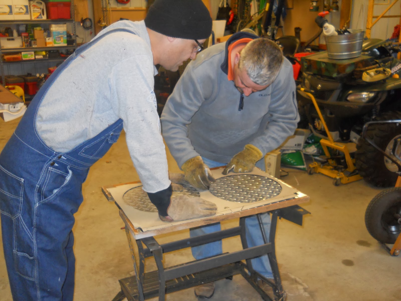
Template Creation
Create a template out of cardboard. You can make lots of mistakes with cardboard. We transferred the measurements on to the cardboard and began testing the fitting. We then mocked up the fans and cut holes in the cardboard. Again we fitted it. Basically any time we modified the cardboard we tested the fit.
 |
| It’s important to act like a total smart-ass and mock the genius you are watching. |
 |
| Normally I would request he use safety scissors like the one’s for kindergarteners but it was his shop, his rules. |
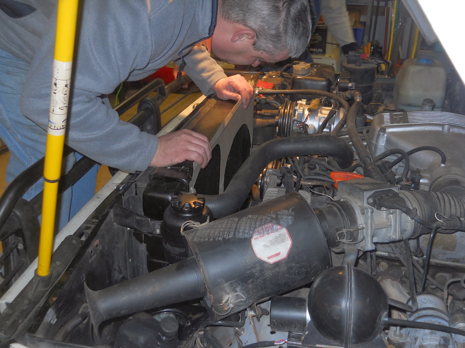
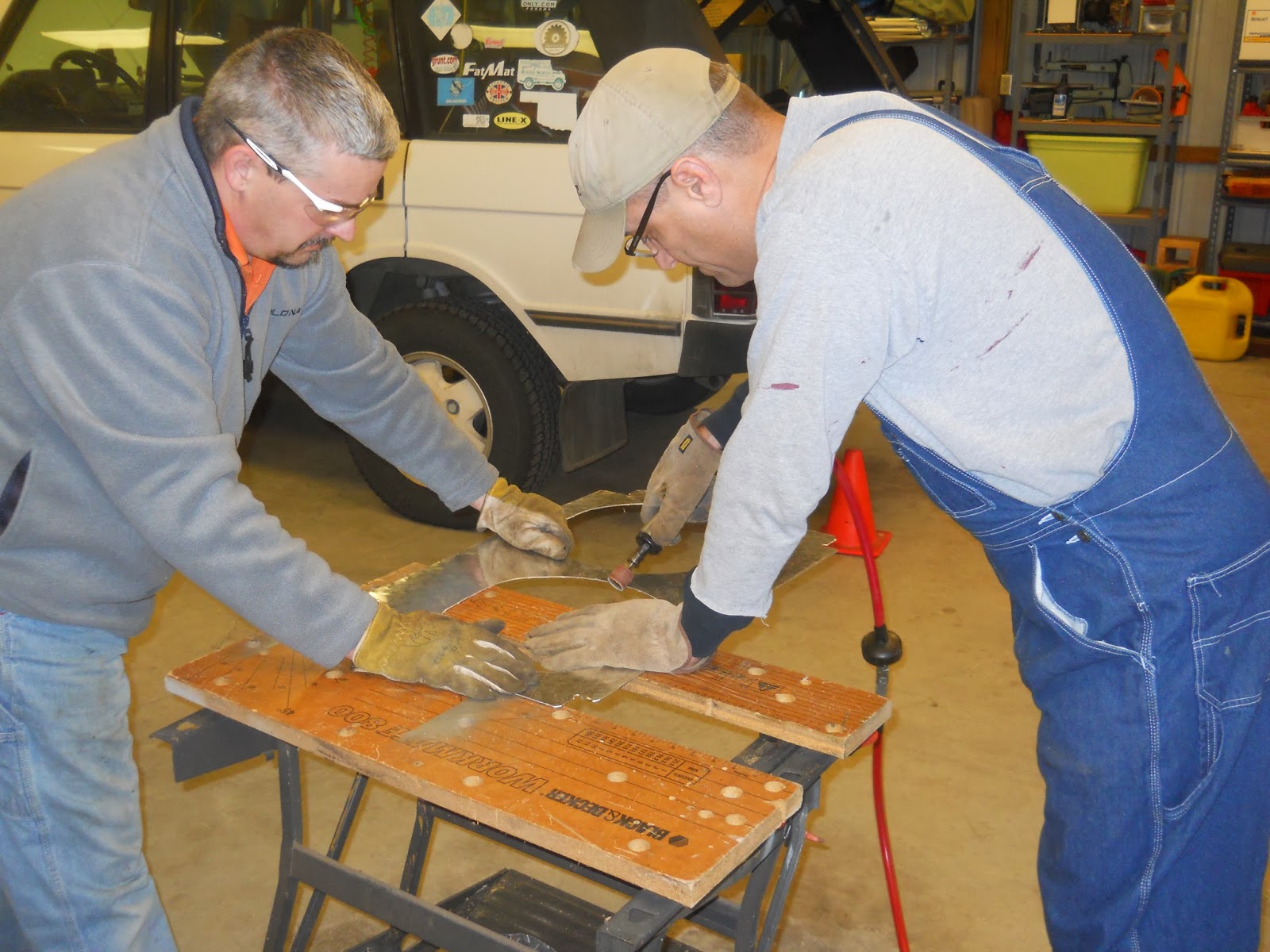
 |
Using a giant crescent wrench the fan was easy to remove.
Normally you need to either have the special tool or rig something up to hold the water pump shaft still.
I’d had my fan out recently so it was no trouble to remove. |
 |
| Checking the fit on the spare radiator. |
 |
| The first of many test fittings. |
 |
Pay attention to the proper explanation of radiator cooling theory.
Me: “Will there be a quiz?”
EGD: “Quiz? Quizzes.” |
 |
| Placing the fans and marking the holes. |
 |
| Test fitting again. |
Cutting the Shroud
We then took the template to the aluminum diamond plate. We used diamond plate because it looks freaking awesome. That, and it is thick enough to carry the weight of the fans and is rigid enough to keep still when the vehicle is in operation.
 |
| Transferring the template to the aluminum sheet. |
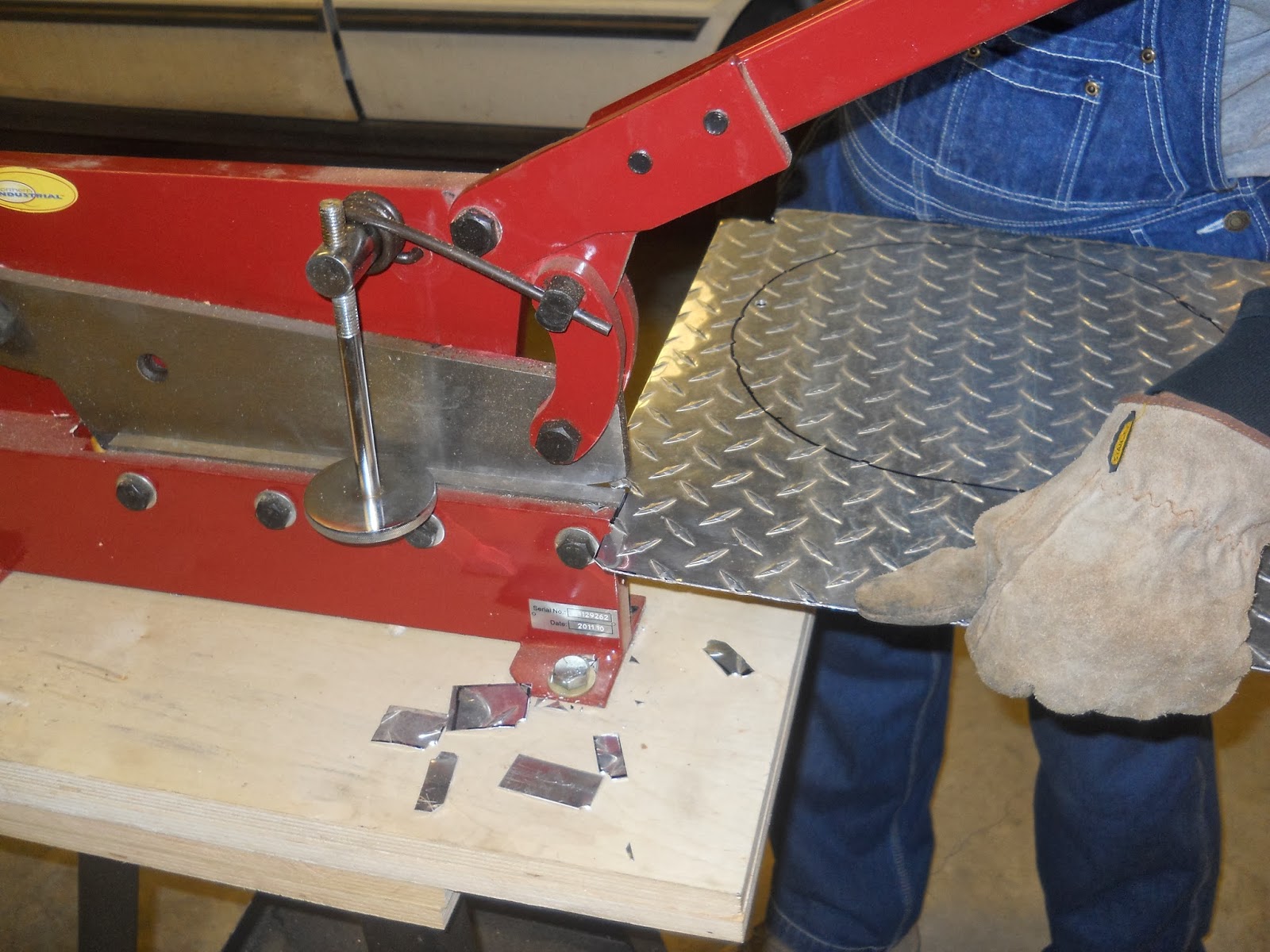
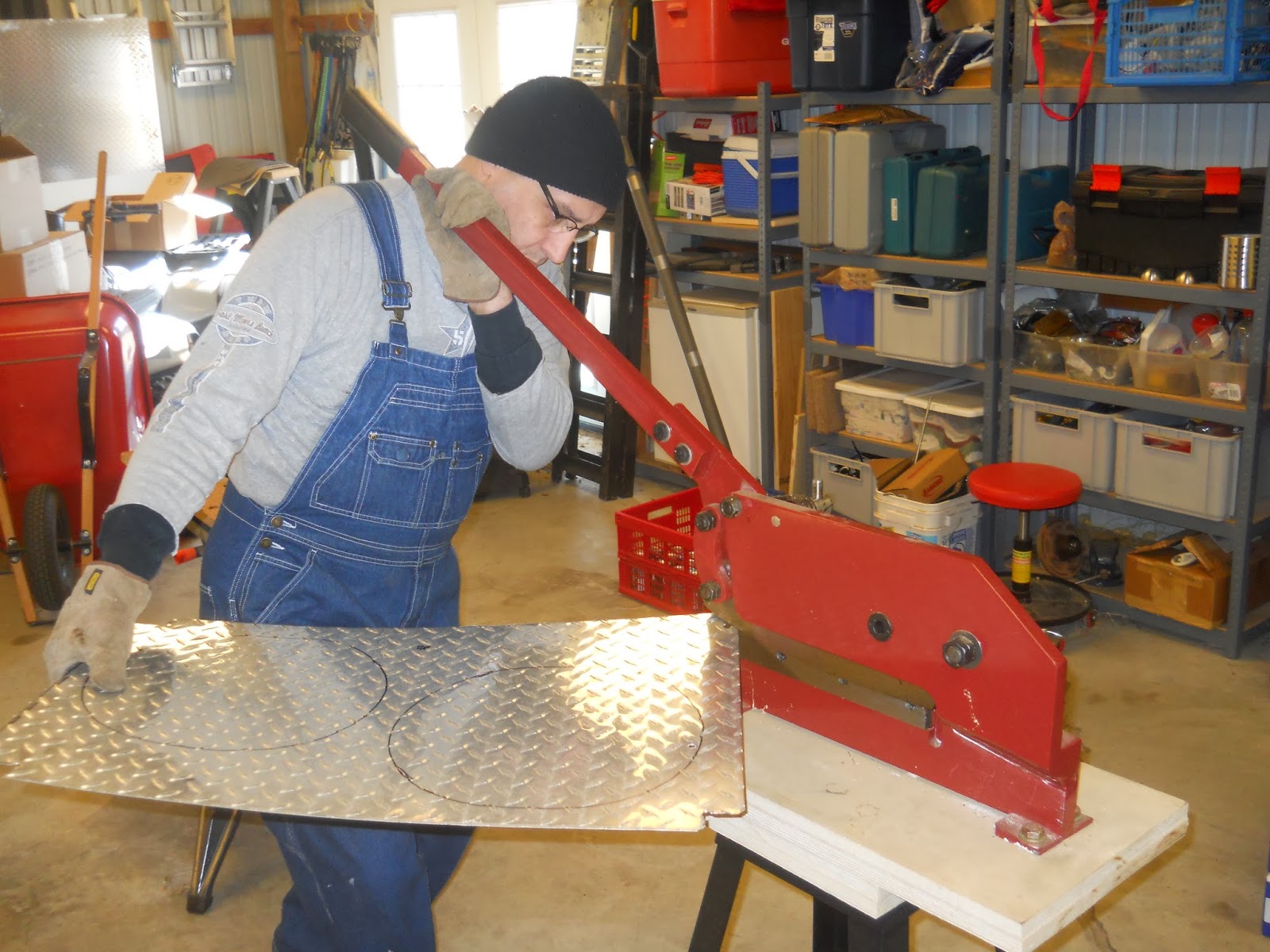
 |
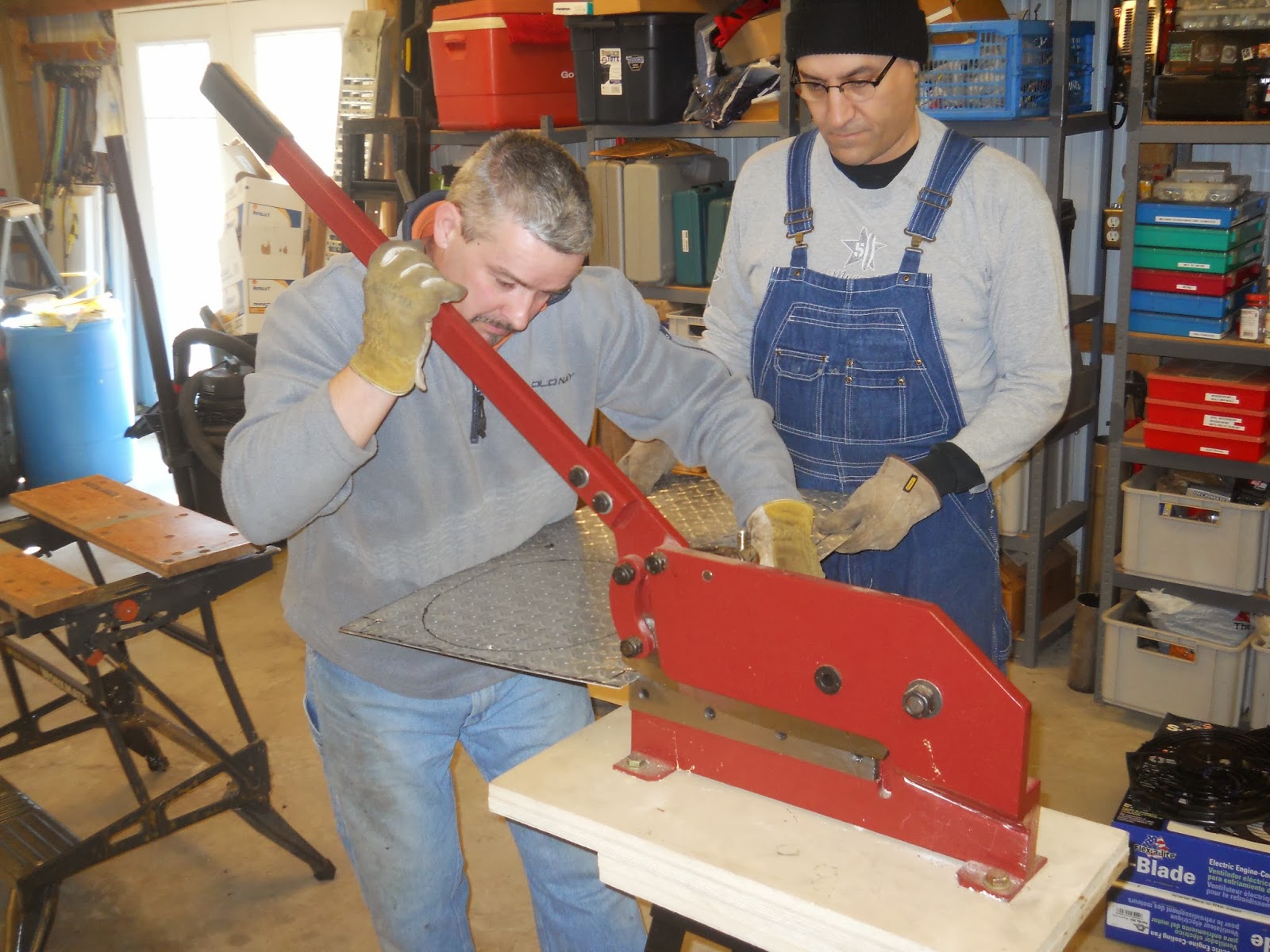
This shear made the cuts very easy. You could also use the jigsaw or tin snips.
Take your time and be careful. The long cuts took all three of us due to the size of the stock. No pictures. |
 |
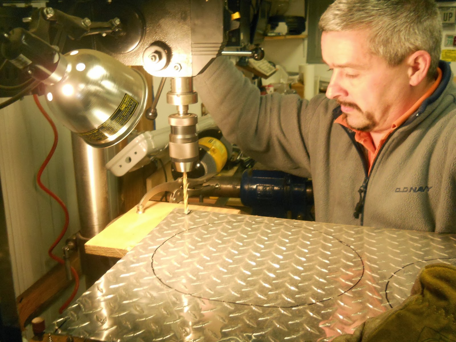
Pro-tip: I learned that if you drill the corners you don’t have over cuts.
And if the sheet vibrates it will not tear at the intersections of the cuts. |
 |
| Every hole gets de-burred with a burring bit. EVERY HOLE. |
 |
| Transferring the fan holes to the sheet. |
 |
I guess you never really ever get out of elementary school.
Sniffing markers. |
 |
| EGD picked the wrong week to stop sniffing markers. |
Testing the Cuts
We then put our shroud on to the radiator and tested the fit. We marked the lower brackets and checked for clearance on the corners. There are parts of the radiator that extrude beyond the plane of the shroud. Instead of bending them we chose to cut the shroud for the clearance.
 |
| First test fit of the shroud. |
 |
| Checking the clearance on our first cuts. |
 |
| Marking the adjustments and the lower bracket locations. |
 |
| Making the adjustment cuts. |
 |
More cuts with the shear.
Tin snips will work for this too,
but, the beginning stages of arthritis require the
use of tools that to most of the work for you. |
 |
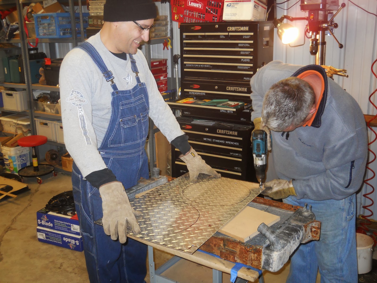
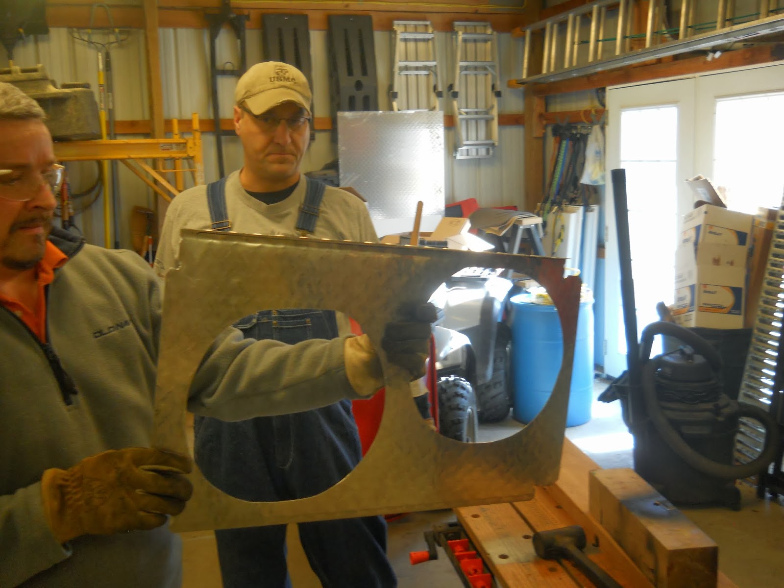
| Cutting out the fan holes. |
 |
And the second hole. These two holes decimated the saw blade.
So if you have to use a jigsaw for all your cuts plan to use more than one blade. |
 |
More deburring this time with an air grinder.
We used two sanding cylinders to deburr everything. |
 |
| If you guessed we test fit it again, you are correct. |
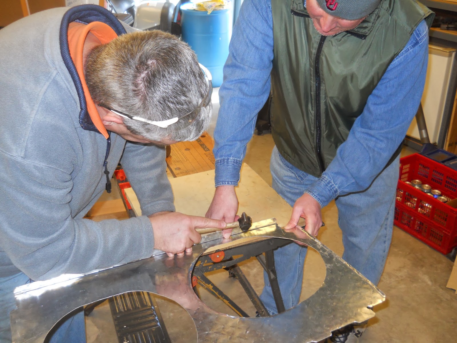
Strengthening
We had some thought that we would want to minimize the flexing of the shroud. EGD decided a 90 degree bend in the top would go a long way to holding the shroud in place and minimize the flex. He also decided we should use a piece of “L” stock to strengthen the between the fans. We had cut away a lot of material and the small area between the fans might flex. And in a total stroke of genius he beveled the fan openings. All this turned out great.
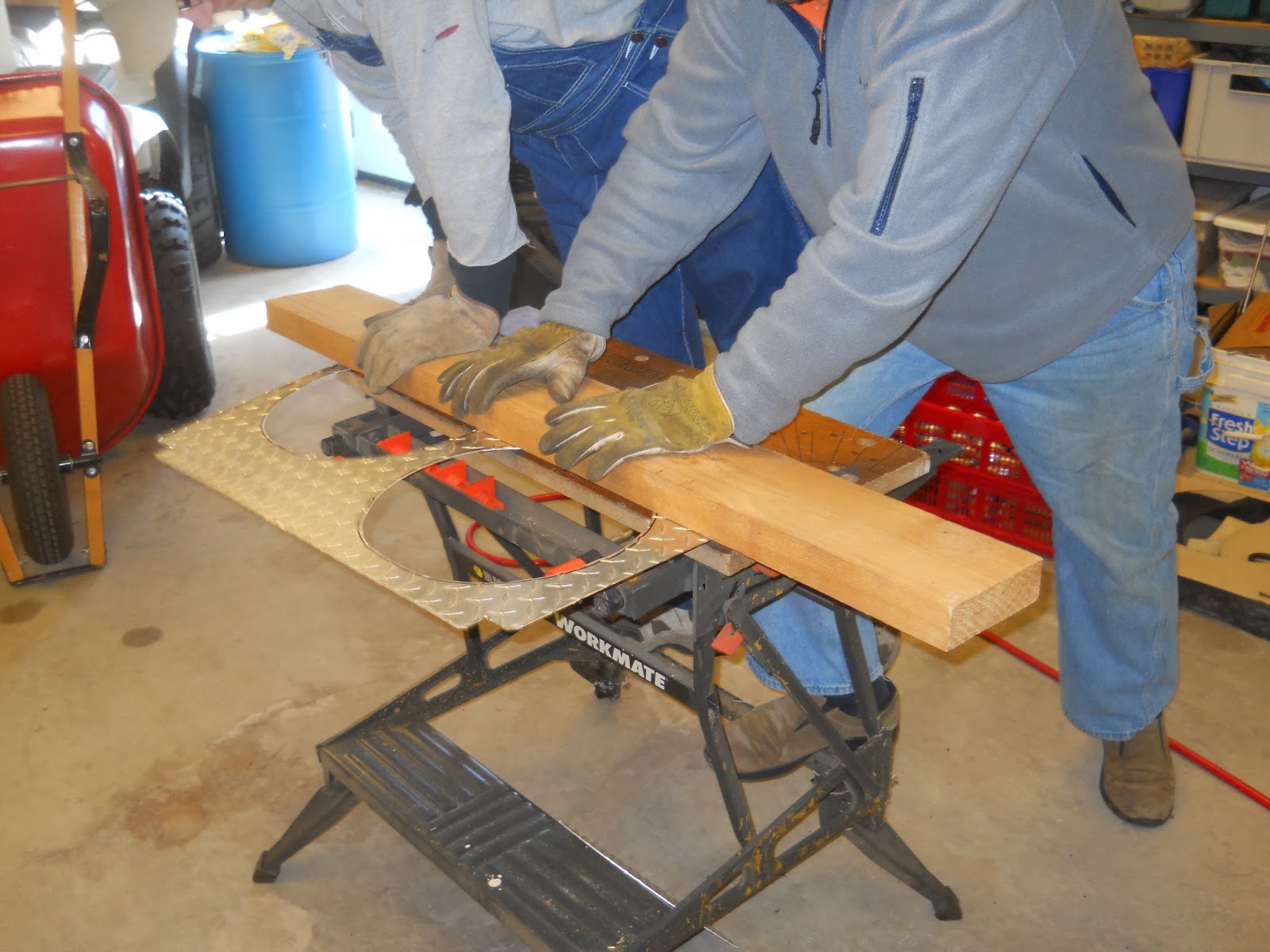
 |
| Craftsman Workmate came in very handy. |
 |
| Bend complete. It took both of us. |
 |
| Dead-blow hammer to sharpen the bend. |
 |
| You can bet your butt we test fit it too. |
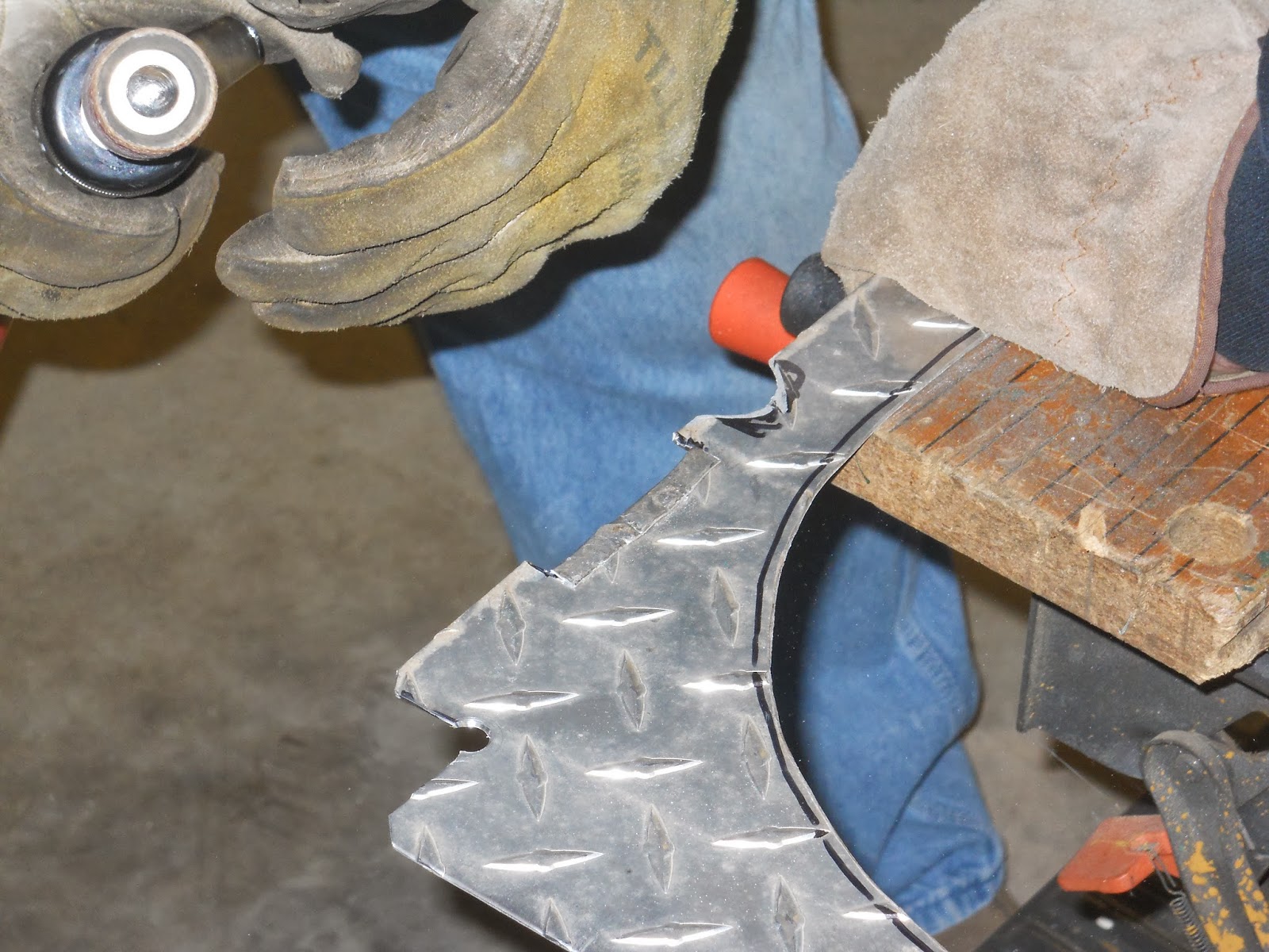
 |
| Adding the bevel to the fan openings. |
 |
| Up close picture. Just a slight bend minimizes the flexing of the material making it more rigid. |
 |
| “L” stock added to the middle to minimize flex and make it more rigid. |
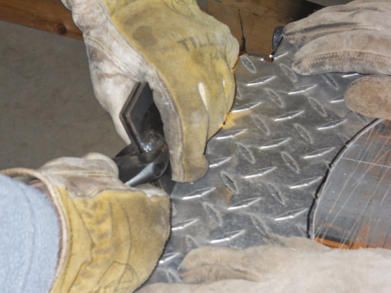
 |
| Drilling for the pop rivets. |
 |
| Deburring never gets old. |
 |
| Pop rivets are magical. |
 |
| Mmmm, pop rivets. |
Final Cuts
We made the last of the adjustments to the shroud. These included a channel for the hose that delivers washer fluid to the headlights. We also cut channels for the lower bracket. This served two purposes. It eliminates putting a fastener of some type on the lower half. There isn’t a fastener on the the original shroud so it seemed fitting. The channel also keeps the shroud from sliding along the radiator. A piece of weather stripping foam was applied to the under side of the 90 degree bend to minimize it rubbing on the top of the radiator.
 |
| Cutting the channel with tin snips. |
 |
Deburring and opening the washer fluid channel. This hose moves a lot beneath the radiator.
So making a channel for it holds it in place and keeps it from being cut by the shroud. |
 |
Interestingly crescent wrenches are not common in Germany.
EGD had modified this one for making bends. |
 |
Folding the edge over.
This increases the material resting on the bracket and adds strength. |
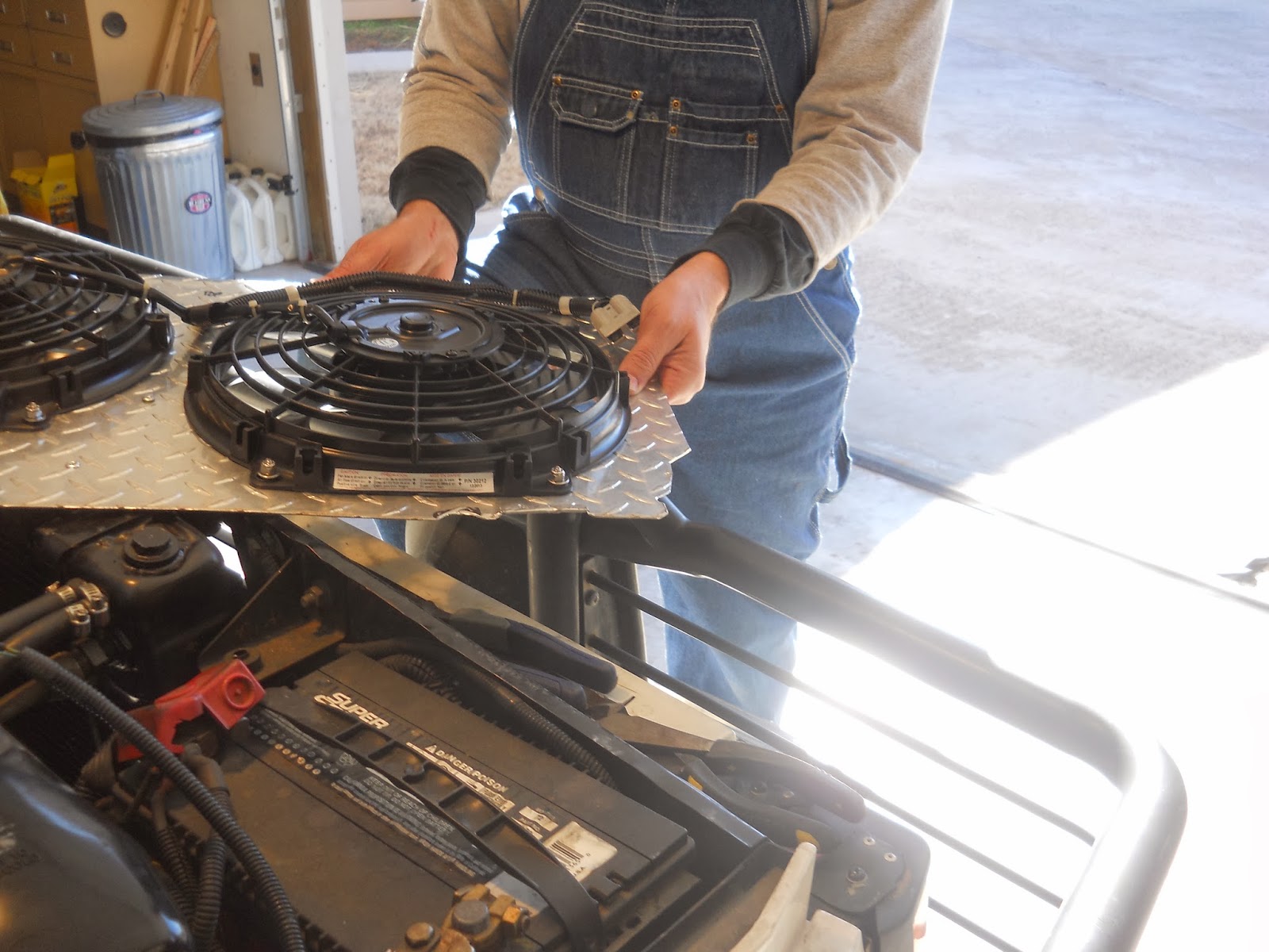
Mounting the Fans
After test fitting the final changes to the shroud it was time to mount the fans and begin the wiring.
 |
| Marking the holes to be drilled. |
 |
| Drilling. |
 |
| Bolting it all down. We used stainless steel nyloc-nuts. |
 |
| Making quick work of it with four hands. |
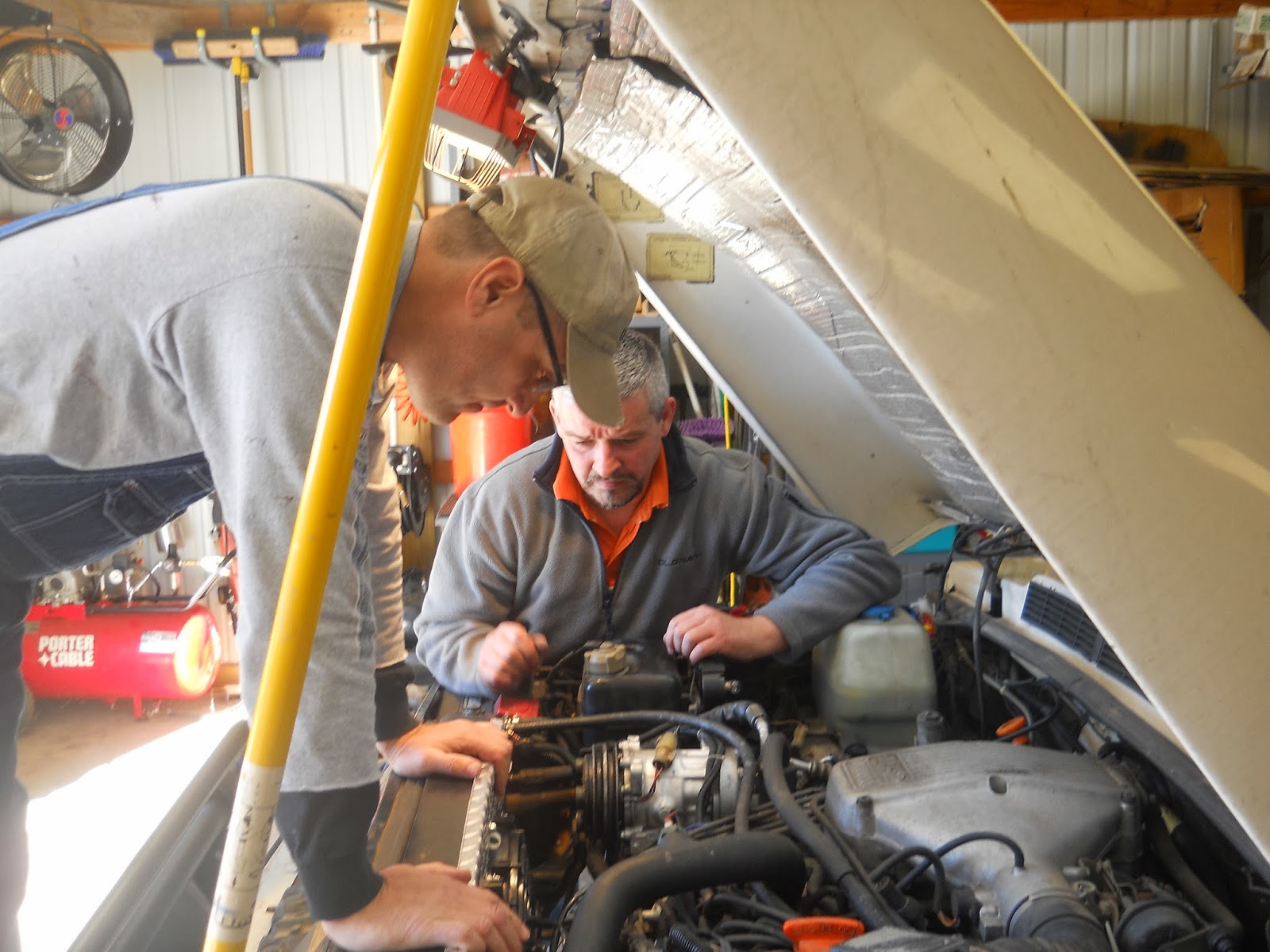
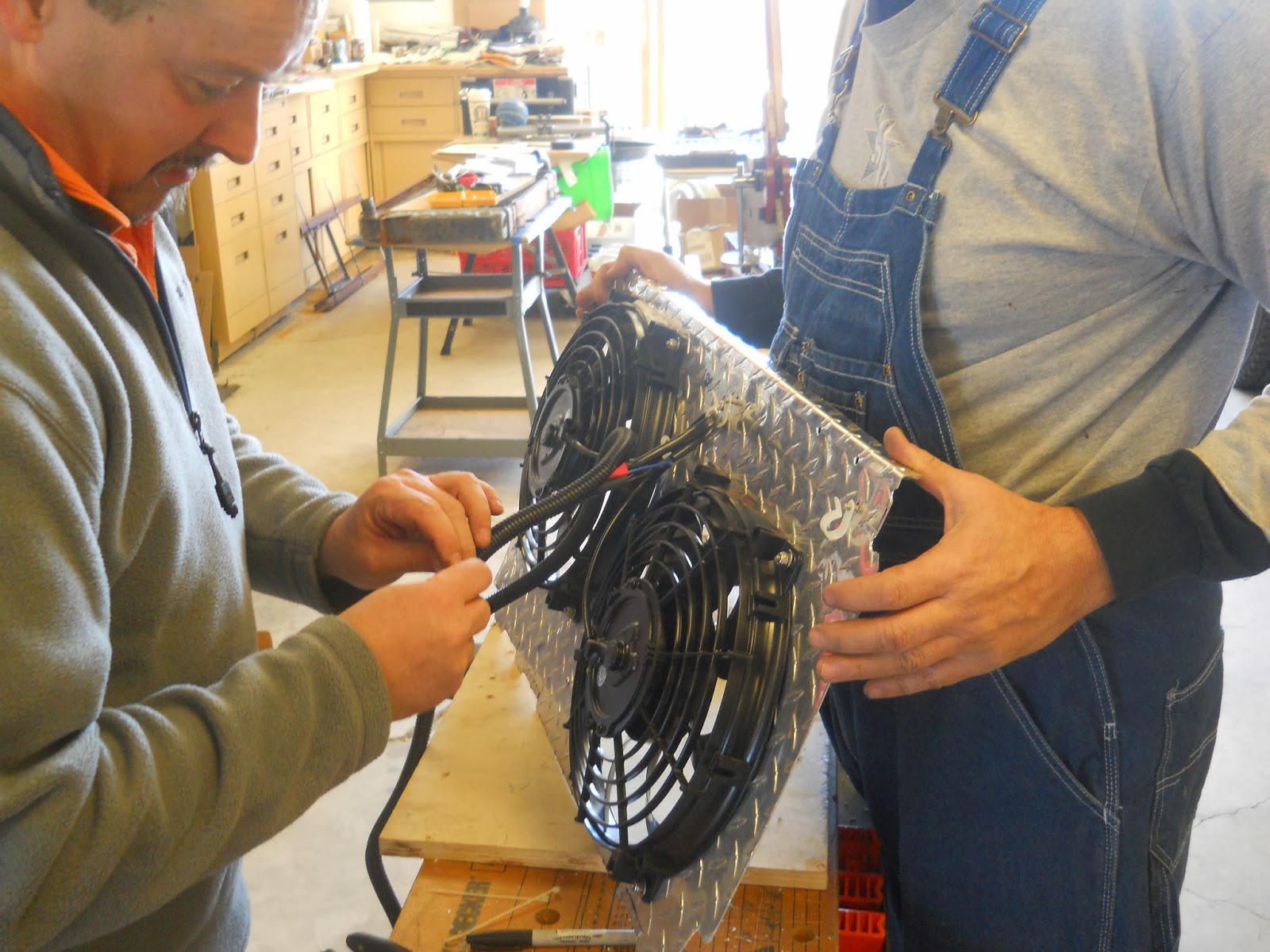
Wiring the Fans
After the fans were mounted to the shroud. They were again test fit. You can never be too careful.
 |
| Test fit and sorting how it would be wired. |
The electrics were then wired up. EGD and Paparazzi Ford did this work while I sorted out a place for the control unit.
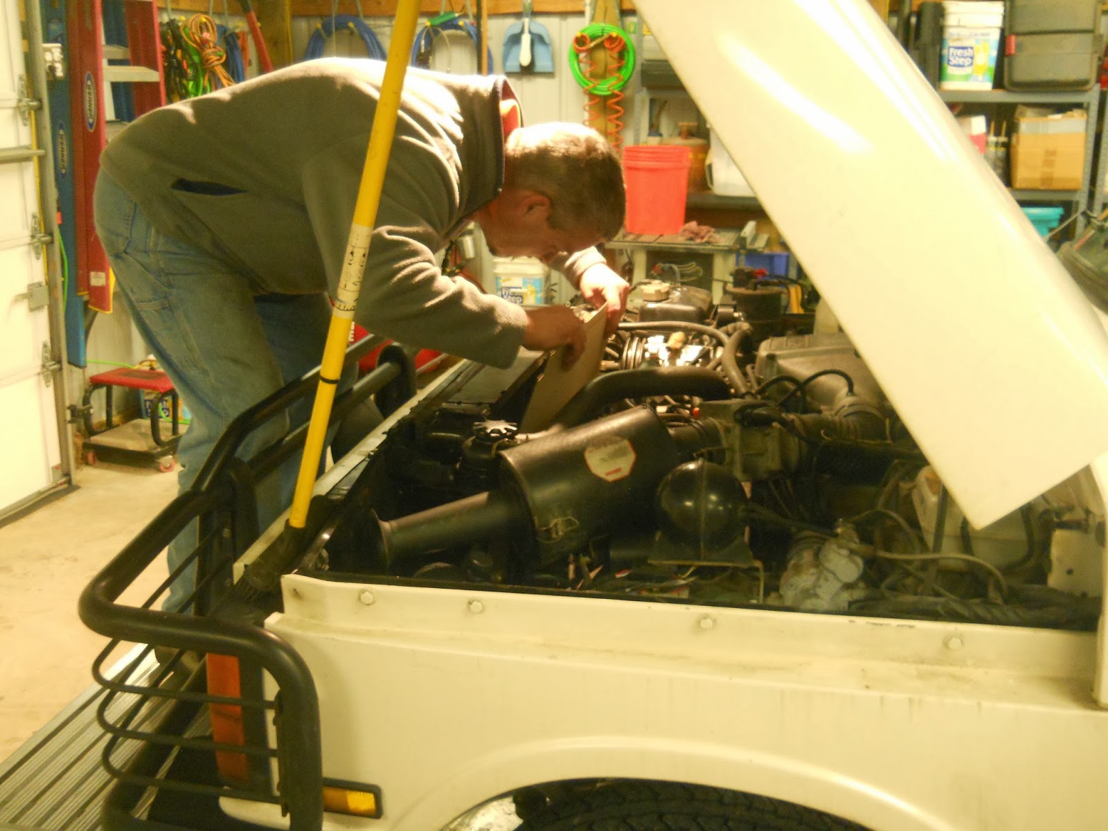
I determined the right side fender to be the best place to located the 4 x 6 inch control unit. Special care was taken to make sure the sensor would be routed in a protected location. It is a fragile tube full of fluid that cannot be bent or damaged. Running that down the inside of the fender seemed the most prudent location.
Shortly after I purchased my Range Rover we had the air ride removed. Knowing this, I looked at the canister on the passenger side fender and it’s plastic air tubes and assumed it was part of this now defunct system. I was wrong. The canister is part of the emissions control system. Unburned fuel fumes are sent back to the fuel tank.
Totally misunderstanding what this thing did, I removed the canister. The bolt fixing the bracket to hold the canister was rust-welded and would not be removed with wrenches. I made the executive decision to remove the entire bracket. I removed the canister which is full of charcoal pellets.
 |
Once the side was cracked charcoal pellets started coming out.
The rust welded bolt is visible to the left. |
 |
| Minimized the mess by vacuuming out the charcoal. |
 |
| An air chisel made short work of the bracket. |
 |
Unfortunately the rust was left.
I will have to fix that another time. |
 |
Considering the number of knives and tools we used this was the only wound during the operation.
I managed to scrape myself removing the bracket. |
While I was demo-ing the canister. EGD and Paparazzi wired up the fans. The kit contains a wiring diagram. EGD had done this job twice before, once on his Chevy pickup truck and once on Paparazzi’s Chevy Blazer. He started wiring and soldering and such. This is a good time to say that every wire was shrouded in wire loom. Wires are not to be left without some sort of protection.
 |
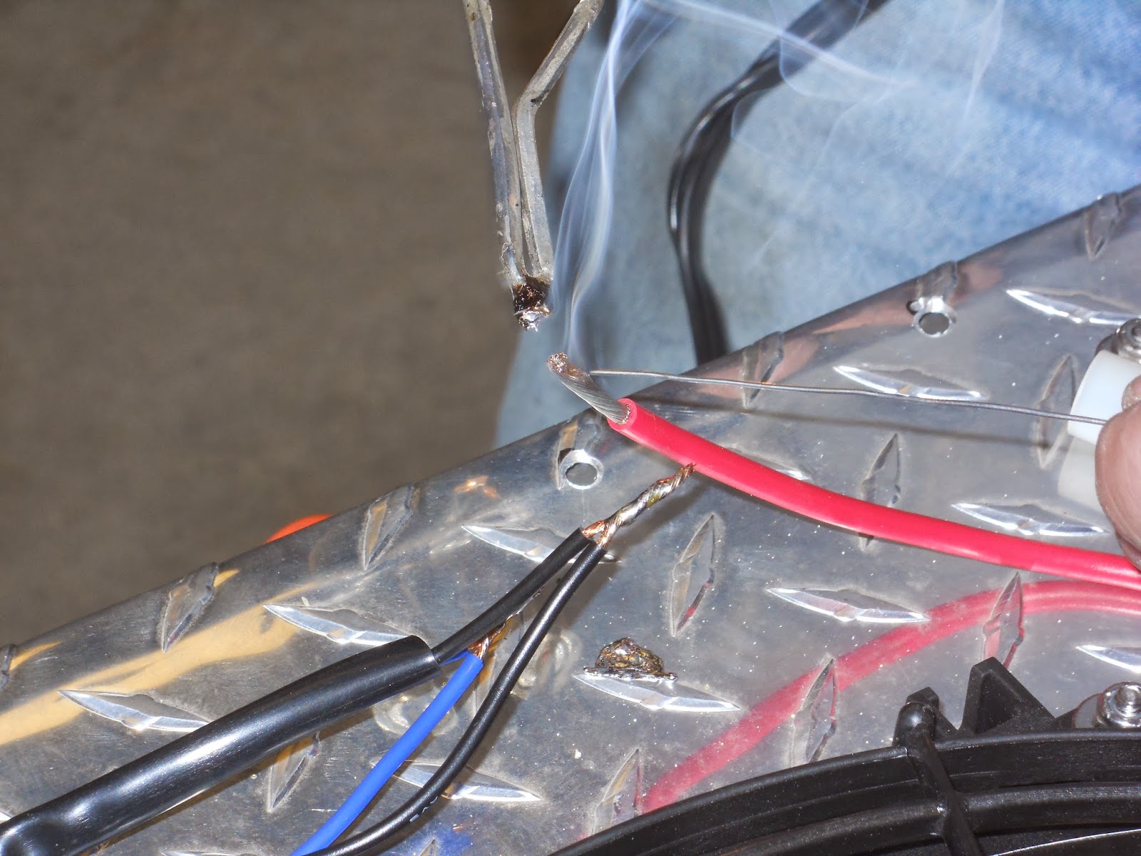
| “Tinning” the ends. |
 |
| Soldering the ends. |
 |
| Color coordinated heat shrink applied. |
 |
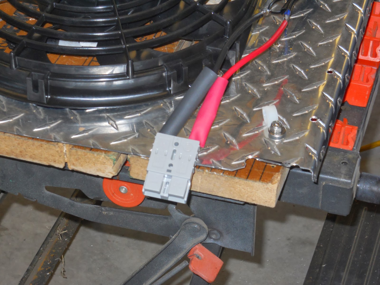
Quick disconnect installed.
These were salvaged out of some old dead uninterruptable power supplies (UPS).
You will need to remove the fans in the future so plan to remove by installing a proper connection.
These are not in the kit that comes with the fans or the controller. |
 |
| Final touches. |
 |
| Done. |
If I get any questions about this project it will be how to wire up two fans. I will say now I didn’t do this part or pay much attention as I was working on other stuff. Follow the directions or call the Summit Racing help line. I was surprised Summit Racing has a technical support phone line. I have called them and they were helpful in determining if my controller would work with two fans like the website said it would.
Control Unit and Final Mounting
We sorted out where the sensor would be inserted into the radiator. We chose the area closest to the coolant out pipe. The logic is as such. If the outlet temperature is not enough to trip the fans, the fans will not be on. If the outlet temp reaches the set mark it will trigger the fans. Placing the sensor at the inlet as the video shows will trigger the fans to come on when the temp is at the set mark coming off the engine. The temp off the engine will almost always be hot and will have the fans running more than necessary. If the radiator is unable to cool the fluid due to (insert condition here) the fluid exiting will be the same or close to the same as the inlet temp. We want the fans to come on when the exit fluid temp is above our set mark. So when the exiting coolant fluid goes above that mark, the fans will come on and cool the fluid so that it will drop below the set mark.
I know that might be a little unclear, but that is how I understand it and I passed my quizzes after the cooling lecture. Your logic may be different than mine or different than EGD’s. He’s a ridiculously smart guy and I’m going to trust he has it right.
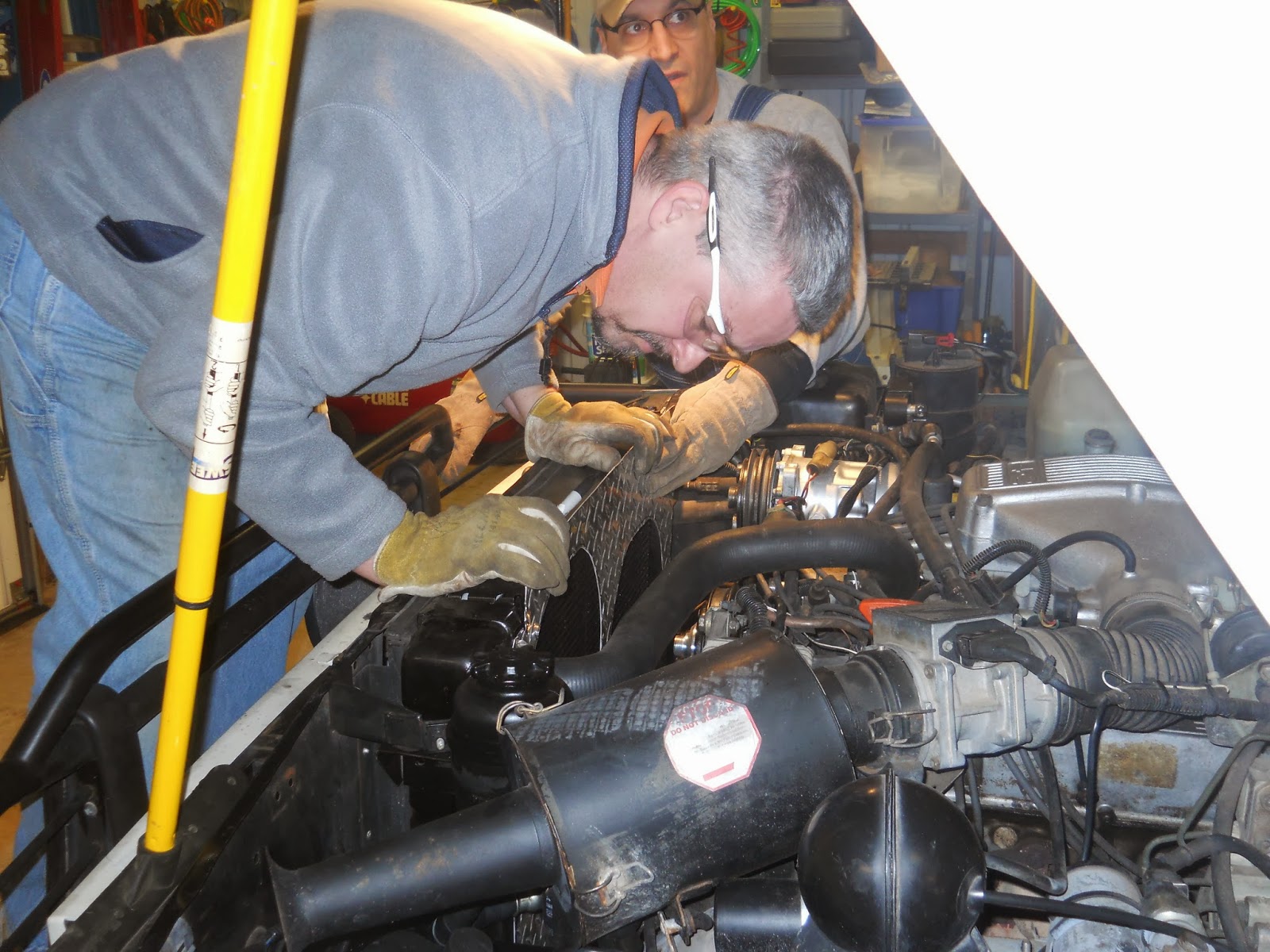
 |
Sensor in place.
Sensor tube inserted into some wire loom and zip tied to the lower hose.
The sensor tube travels up the inner wing to the control unit located on top the wheel well. |
 |
Once the sensor was placed we needed to adjust our shroud to accommodate it.
You can see the additional notched out part at the bottom of the shroud near my hand. |
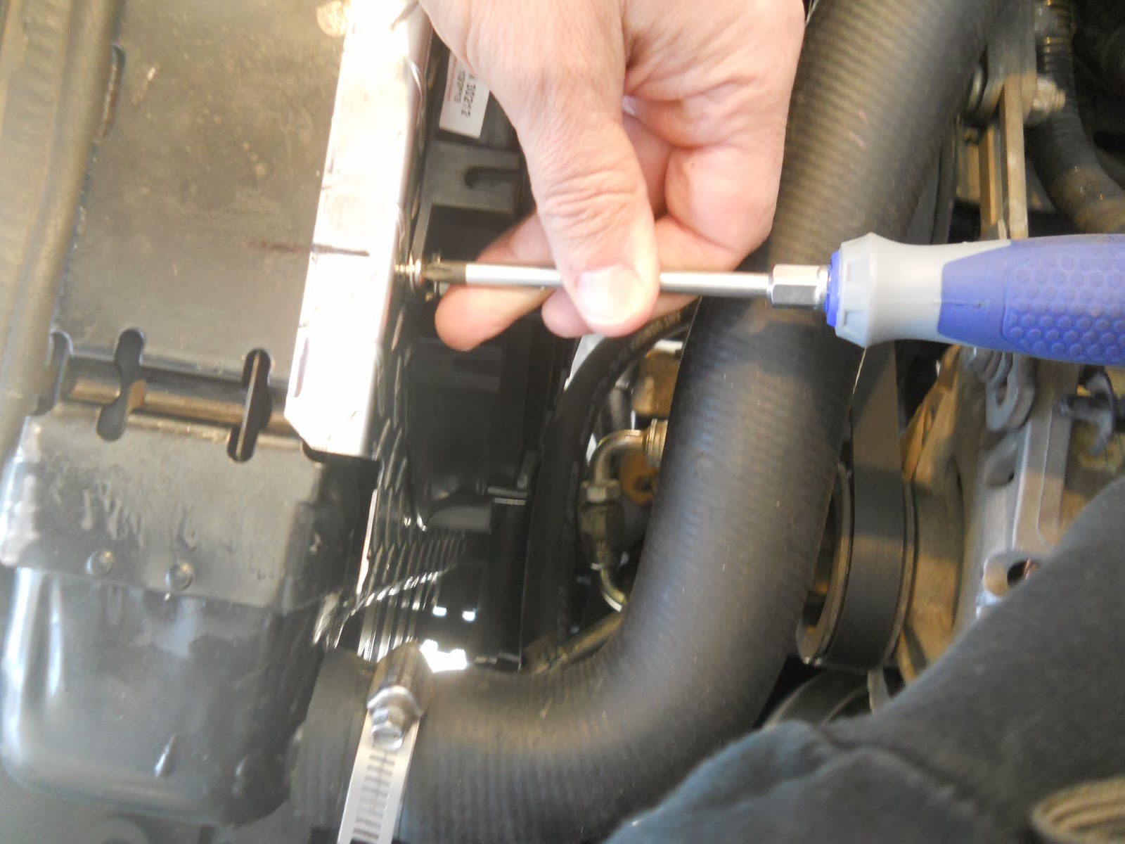
 |
Screwing the shroud to the radiator.
We used the existing holes on the radiator. |
 |
| Wiring loom routed and installed. |
 |
| Wires plugged into the control unit. |
 |
| Rough location and plugged in. |
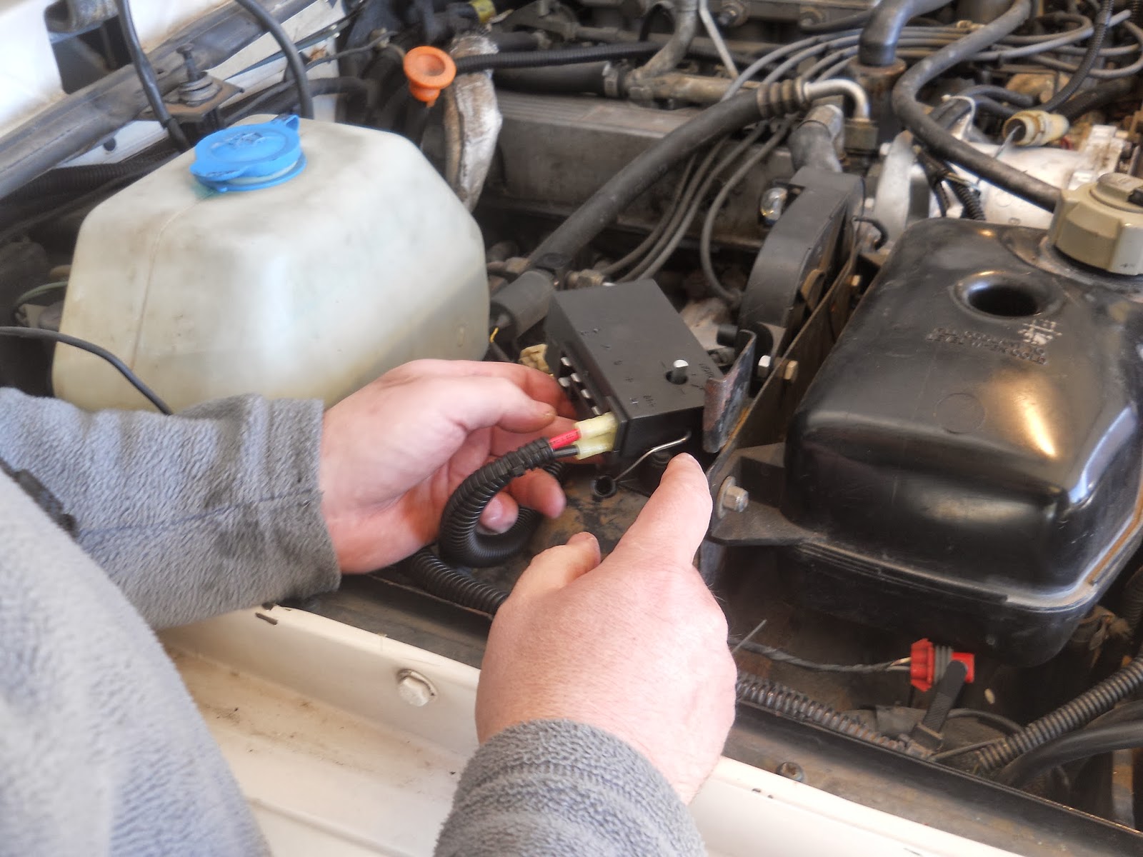
 |
We received quite the teasing from Paparazzi over our consultation of the wiring diagram.
The control box is marked with only single letters that are not necessarily clear as to their function. |
 |
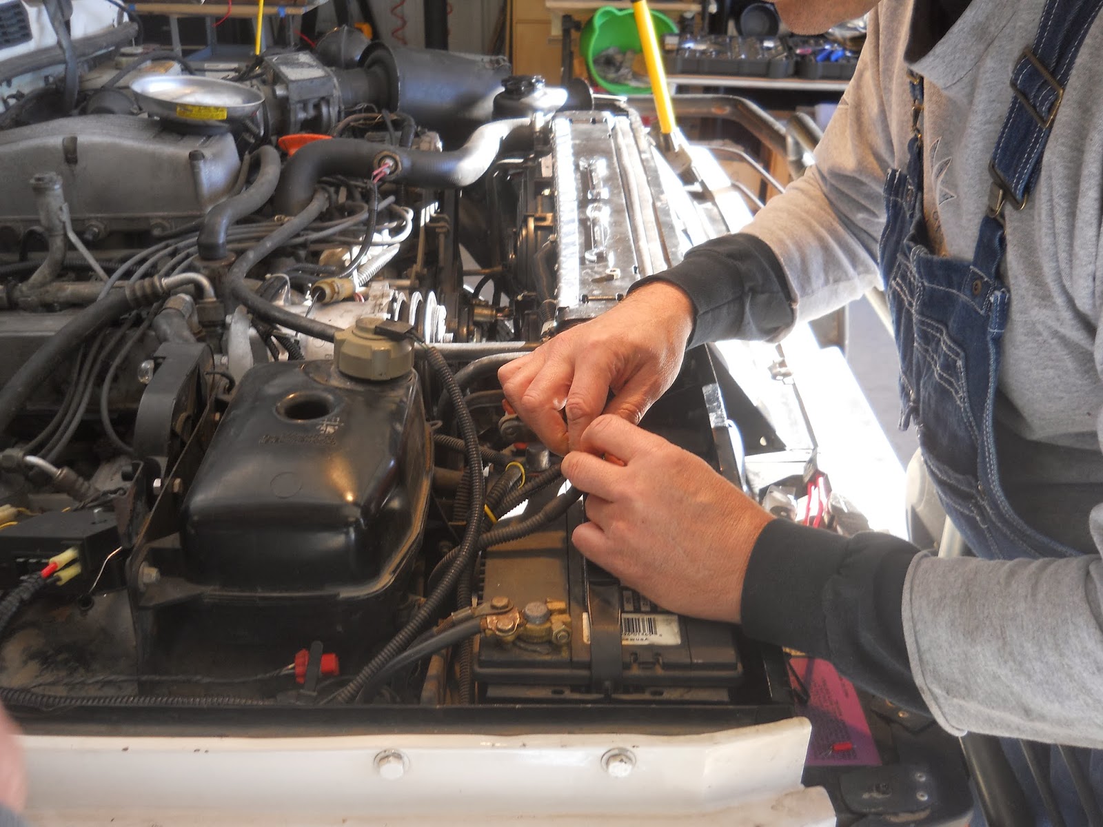
| Wiring the connections to the battery. |
 |
| The factory wiring annoyed EGD enough that we had to rewire the batter connections. |
 |
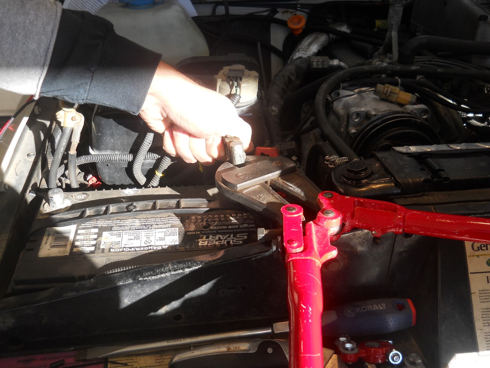
Bolt cutters to cut the battery cables.
Both of the girly men tried to close the bolt cutter to no avail.
Finally I took over and cut the connector.
They claim they did all the “hard” work and I just finished it. Whatever. |
 |
| Cutting back the insulation. |
 |
Corrosion. You can see the green on the wires.
It was cut off. |
 |
| More wires attached to the control box. |
 |
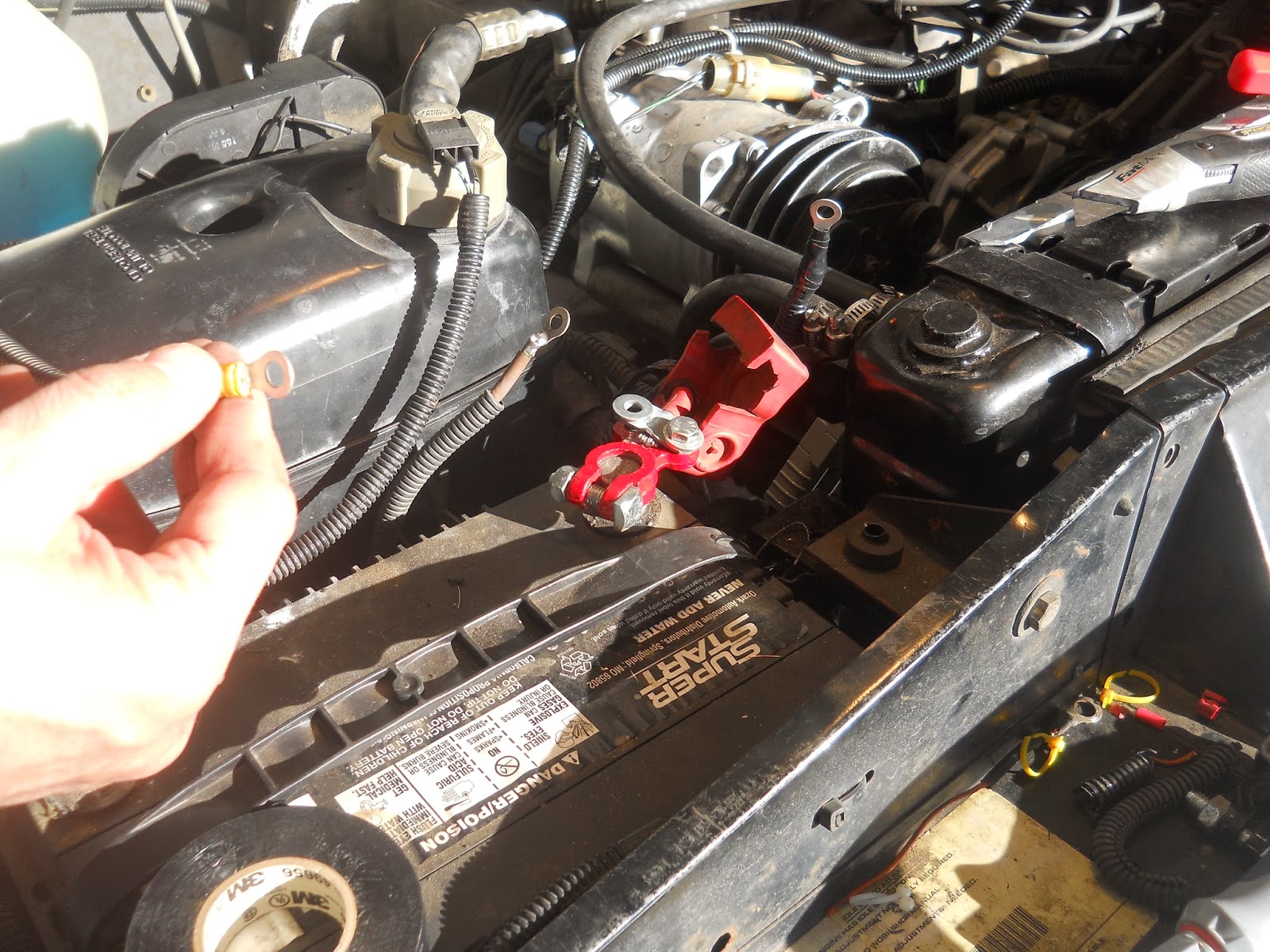
| New battery connectors and wires getting crimped and prepped. |
 |
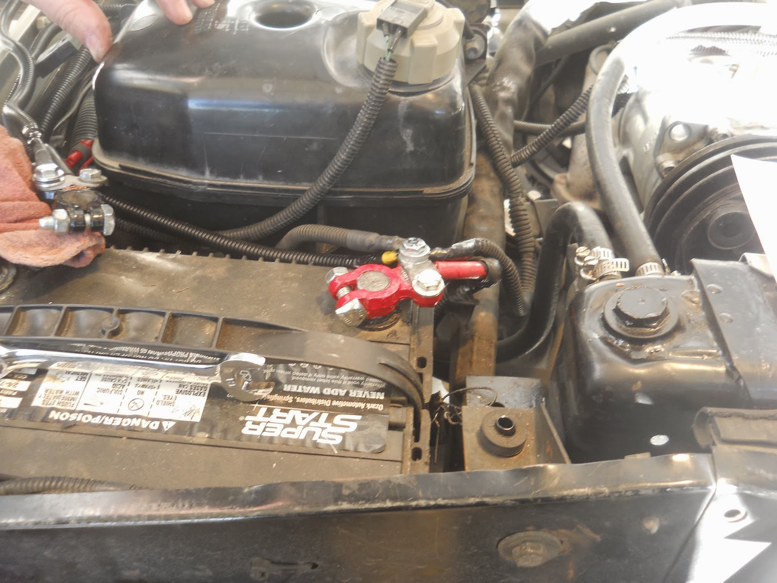
| Wires mounted to battery terminals. |
We got all the control box connections made. This control module offers a manual override option. So I ran the wires into the cab and sorted out a suitable location for the override switch. This override switch turns the fans on. This allows you to engage the fans in the case that the temp climbs and the adjustment on the control box is insufficiently set to engage the fans. I believe there is also a control box that has a manual cut off switch. If you were doing a water crossing you would not want your fans on for that so you can manually override the system and shut the fans down. Water crossings are uncommon and if ever faced with this situation I’ll just unplug the power to the fans.
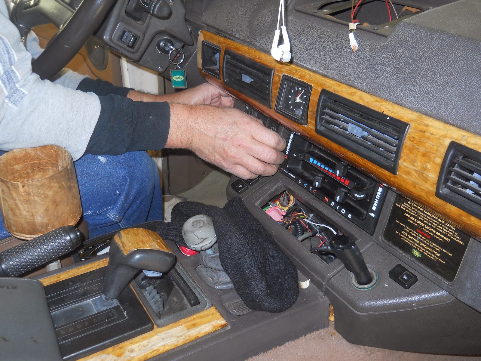
I ran the wire down the wing and through the access hole behind the cowl. This is where the wire-fishing rod came in handy. We attached the wire and just poked it through and down to the foot well. I ran the wire under the air conditioning lines and through the dash cowling over to the switch panel.
We needed a ignition switched positive and ground to complete the over ride switch install. We also wanted the light on the switch to be illuminated when the switch/fans are on. We wired this to the cigarette lighter positive located there next to the radio.
 |
| Control unit installed with all wires attached. |
 |
Removing the switch panel to install the override.
I chose to remove the windscreen defrost switch.
I don’t have a electric defrosting front windshield. |
Testing
We tested the switch first. I turned the ignition on and flipped the switch. We didn’t have anything at first. EGD checked the wiring and we noticed the connectors were poorly fitted and needed some adjusting to make better connections. With that sorted we tried it again and the fans spun….the wrong way. We had wired them backward. So EGD swapped the wires and we tested it again…success!
With that sorted we fired up the engine and waited. It seemed to take a really long time to get the engine up to temperature. Once it got there, the fans came on. I was watching the temperature gauge and the fans came on with the needle reaching just below the half way point on the gauge. That was fine.
A test drive down a section line and back had the fans keeping the temperature rock solid. The air temp outside was 52 F. EGD said some adjustment would need to be made when Spring comes and then again when Summer hits.
The drive home was great and the needle was solid as you could ask for. I did notice a slight change in the throttle response. Not enough to make someone say, “Wow”. But enough to notice.
Difficulty Scale
On the Okierover Difficulty Scale this job is a Four. Mostly because of the skills needed to fabricate a shroud and wire the control unit correctly. As explained this is my scale. For someone like EGD this might be a two or three on a scale of five.
Conclusion
Like I said this was a loooooong post. This post in the blogosphere is the equivalent War and Peace in the novel world. It actually took an hour longer to go through all the pictures and write this post than the actual project took. Paparazzi Ford took 421 photographs. And he promised he had left us a little surprise.
 |
| Maybe he wasn’t all that happy about taking pictures after all. :/ |
Hopefully this post is helpful to someone who is considering this project for their Land Rover. I’m sure a year from now someone will send me an email and is going to want some specific detail of this project answered and I’m not going to be able to recall how that particular bit was done. Hopefully the technology will get better. Already in 10 years the control unit has been invented or created or manufactured, whatever. In the past you had to incorporate your own thermostat and relays.
In the end, I won’t have to worry about exploding cooling fans, failing viscous fan clutches, and my heater gets warmer about a half mile sooner on my morning commute than it used to in the month of January. All my problems didn’t go away. I just have new problems to worry about. I still have to worry about fans failing only electrically now. I also have an added concern that the controller might fail someday.
On the good side I’m hoping for a little increase in gas mileage. EGD saw a 2 mile per gallon gain when he switched his pickup truck to electric fans. Two miles more per gallon would be nice. I will report back in the coming months pro or con.
Thanks for reading my version of War and Peace this long post, and Happy Rovering.


I might have missed it, but can you give a status update on this mod? How did it hold up during the summer?
Status Update. This worked great. I am not sure I gained any more gas mileage, but it is more responsive. It worked excellently through out the summer. While crawling along the trails at SCARR it worked flawlessly.
That’s good to hear since between OKC and SCARR you see the same conditions I do here in Dallas. I’m looking at replacing my radiator and got sucked down the rabbit hole of researching electric fans and remembered this great post.